Shift contours: problem with BCPs

I think I might have seem this elsewhere on the forum, but couldn’t find it again.

Anyways, I have certain situations in Glyphs 2.5.1 in which I select on-curve points (with or without their BCPs), move them (either with the arrow keys or the dragging), and the BCPs don’t shift by the same amount.
Demo here, with on-curve points confirmed as tangents, then shifted right 1 unit and shifted back:
shift%20problem-bcp

This was one such thread: Angled handle snapping threshold

Your connectors look exactly what mine did when I encountered the problem: a very short handle opposing a very long one. I solved it by changing the UPM to 2000 with a grid setting of 1:1 which allows for smaller adjustments, then utilizing mekkablue’s plugin Show Coordinates of Selected Node, going through the font and correcting the angles of the BCPs on the connecting strokes one at a time until they matched. A lot of work to be sure, but well worth it because nothing ever moved incorrectly after that.

I use his plugin regularly now on every angled stroke I make.

Thanks, George. But I’m describing a simple shift of all selected nodes (with their BCPs) by the same amount; I don’t think it involves snapping. Given the gravity of this problem, my unfortunate workaround for now is to create outlines in FL and copy-paste into Glyphs.

@tgrace – I watched your demo again several times and what I see is that it does involve snapping of the type I described. Glyphs is attempting to make the angles on either side of the node congruent by changing the angle of the longest handle – which also changes the curve. The most obvious example is the node on the right side. That is exactly the same thing I encountered with a stroke design which is identical to yours.

A way to verify that is to have the plugin active and check the angle values. If they don’t match, that is the cause of your problem.

I installed the plugin and checked the angles and they are indeed different. Before the shift they are -118.5/-116.6° and 64.2/68.2°; afterwards they are -116.1/-116.6° and 68/68.2°. So, you are right.
It seems that turning a node from a corner point to a smooth point, like what I did at the beginning of the demo, isn’t visually happening when a node is dbl-clicked, though the change is being stored somewhere. Shifting the node or a bcp applies the change visually.

If you have a lot of similar instances to the design you showed above, you may want to try making the butt of the stroke flat (as in not have rounded corners), and then apply the rounded corners by using corner components. I can’t vouch for the accuracy or consistency in that approach, but it may be worth testing.

Making the corners sharp would indeed work but in my case, which was exactly the same as tgrace’s, would not have fit the soft design of the type. Components would not have worked for me due to the variability of the strokes.

That is the point of the green smooth connector. Whenever you move any of the handles, it tries to realign the other. If you do not want that, switch it to blue corner connectors. (Either double click the point or select one or more and press the Return key.)

Try to avoid very small handles on a coarse grid. You will run into grid rounding problems. Either use a finer grid where rounding problems are minimised, or follow @mattymatt’s suggestion with corner components.

You can adapt and scale corner components, or define different ones.

Matt, I will need to look at this more closely, but I feel this will be difficult to use, for the same reason of variability George describes. Maintaining a repertoire of components doesn’t address the fundamental problem: a green node only becomes smooth when I touch a handle. Can we change this to when I make it green? Until that happens, no green node can be trusted as smooth just by looking at it.
greenNode

Select one of the adjacent offcurve point (like in the original example).

Selecting an adjacent offcurve point fills the circle; no other change.
What should happen?

No, because the software cannot guess for you which handle should be aligned to which other handle. Or to something completely different, like an average angle between any reference points. Chances are, all of these solutions are unlikely to give the intended result, all of them require reworking, so that would not save you an extra step.

However, as soon as you do move a handle, it is clear what you want.

This has been amply discussed on this forum. I’ll dig up the link and add it here.
UPDATE: This is the thread: Smooth points not smooth? - #7 by AlexScholing

Thanks, Rainer, for digging up the previous thread. I would have posted there if I had found it.

“No, because the software cannot guess for you which handle should be aligned to which other handle. Or to something completely different, like an average angle between any reference points. Chances are, all of these solutions are unlikely to give the intended result, all of them require reworking, so that would not save you an extra step.”

I agree with the last sentence, not the first two. From FontLab:
greenNode
I have to rework the curves, yes, but I know they are smooth because they are green. Conversely, they are green because they are smooth. This is not the case with Glyphs: green does not necessarily mean smooth. When I review outlines, not just create them, I want the color to have consistent meaning. This is important feedback for quality assurance.

Update: for interpolations, the same thing appears in FontLab:
56
Double-clicking the point makes them smooth.

Is there any way that such faux-smooth points in Glyphs can be kept blue? Maybe by checking against a threshold for the difference of angles between the two handles, for example?

Yes, there is. The most convenient option is @TimAhrens’s Harmonizer, which offers a Dekink Only function. You can add it as custom parameter to your instance. Very convenient after interpolation, like the example you cite.

Then there are scripts, like my Realign Handles or Dekink scripts from my repo.

A few thoughts:

  1. Technically, once your handles are not exactly horizontal or vertical, you can bet they are not completely smooth. Think grid rounding.
  2. The word ‘smooth’ is really misleading. The segments may still not have the right curvature relative to each other, even though the handles align. This is where plug-ins like SpeedPunk, the Remix Tools, and SuperTool help (see the Extend page).
  3. There are different ways to round handles onto the grid. So QA based on node colors is error prone just as much.
  4. The difference between smooth and not smooth is not stored in the compiled font, it is just a convenience that the editing UI offers.
  5. We choose to do some things differently than other software, for good reasons. (Compare the way we add handles to segments.) Green and blue marks the editing behavior of the node, not the state of (good enough) smoothness with the two surrounding points.
  6. The example you show in the animated GIF shows everything that is wrong with this snapping behaviour: You have no control over what snaps to where, thereby messing up not just one, but two segments in one go. What if one of the handles is already where it needs to be, and only the other one needs to be aligned? A frequent case in many people’s workflows. Glyphs gives you that control.

Yes, it can, as some Realign Handles script proves. I strongly agree with Tom, double-clicking a point from corner to smooth must always align the handles immediately, either to an average of the two angles, or when one of the handles is already horizontal, vertical or at 45, only the other should move.

Simply because when a user double-clicks, the point is intended to become smooth, and in doing nothing, you do not respect the intention of the user. It causes confusion, else this thread would not be here.

Additionally, when the user double-clicks, the eyes will be focused on the point in question, so if the smoothing causes undesired results, it can be corrected immediately.

By only making the point appear round and green, you are putting the user into a false belief that the point is as smooth as it can be, when it isn’t. Glyphs is not being honest here.

Furthermore, all other outline editing software manages to align handles when points are turned into smooth, so that “Glyphs can not guess how to do it” is a hollow argument.

Different curvature on both sides of the point is also not a great argument, because the eye can handle a huge amount of different curvature, think straight-curve pink triangle connections. Kinkiness is often more eye-catching, at least in real life.

And think of all those poor users that have turned away from other font editors, and did not have the time yet to read the enormous amount of great threads in this forum. They expect points to behave like in Adobe or old font editor software.

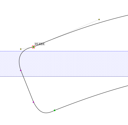
Having the handles jump around when shifting part of an outline is not logical, shifting should keep (grid induced) kinks. Especially in the gif animation at the top, where the long handles (with probably a carefully chosen angle) jump wildly to the constraints of the shorter handle. Glyphs is making an unwanted design decision for the user, which is plain wrong.

Thanks Tom for making me realize why I find outline editing in Glyphs sometimes disturbing.

I agree with two things:

  1. the app currently does not display smoothness properly, it only displays the behavior of the node; we have discussed this omission internally, and we are thinking about a solution. (Please do note, however, that FL does not do a better job at this, as demonstrated above.) The key is that there is a difference between the behavior of the connector and the status of the connection, and the distinction must be clear. We only do the behavior, other apps mingle that, and I don’t think that this is less confusing.
  2. A very good point is: what should happen if the complete path is moved (or a section that completely encompasses the connection in question). I agree that the current behavior is unsatisfactory. One problem we have: if we agree about shifting (and I think we do), what about other transformations: scaling (and especially unproportional scaling), rotation, shearing. Mirroring can safely be assumed to be treated like shifting, I guess.

Thanks, Lucas; this is precisely what made me start this thread, and you’ve said it better than I did.

Rainer, thanks for the tips for Tim’s Harmonizer plugin and your two scripts; I will have a look at them. I agree with your thoughts on the limits of ‘smooth’ against the grid. Furthermore, the image of FL’s behavior is, I agree, problematic, and illustrates what you’re saying. There is room for improvement.

I don’t understand. Why can’t behavior and status be unified? Behavior determines status. Can’t the reverse be true? Green = smooth (within the confines of the grid), at the moment it is green; not after it has been adjusted. Then no-one is confused.

This could all be done with the point type in mind, after points behave as labeled. If I knew that my outlines have green points that are actually smooth, then I accept that scaling and rotating operations will do their best and may change the curve quality of my original outlines. I’ve become used to the double-clicking of a corner point as essentially a ‘smoothing operation’ (Software: ‘you’ve made a decision, I’ve responded as best I can, now deal with the consequences to your curves’).

Shifting is simpler, since all points are moved by the same amount, is that right?

It is technically impossible. Not just diagonals on grids, but especially linear interpolations will produce the kinks like the one you pictured above.

I could think e.g. of either a third color (yellowish for instance) or a halo for indicating a green point that needs updating.

I have a look.

With the FontLab menu entry: Contour > Correct Connections, all nodes are checked and made green red or pink, whatever fits, within proper tolerances. This also happens if you cut and paste outlines. In the interpolated instance, colors might be wrong, a bug which could easily have been solved by applying that menu command automatically while interpolating.