I have converted 6 single files from FLS to Glyphs3 and cleaned them up in Glyphs3. Most of them are a complete instances as well as a master but I want to interpolate between 2 of them, XtraBold and Medium to achieve a “Bold” layer to complete the family. Although I have consulted the Handbook and gone through the Tutorials, I can’t manage to do it. I have sent in 2 crash reports that have ensued in the tries. I know I am the “F*ng New Guy” but would like to get clear on what I am doing wrong.
I’m not sure about G3 but in Glyphs 2 those red corners on the top left of the letters mean that those glyphs are not compatible with each other.
That usually makes them not interpolate correctly.
Things to check:
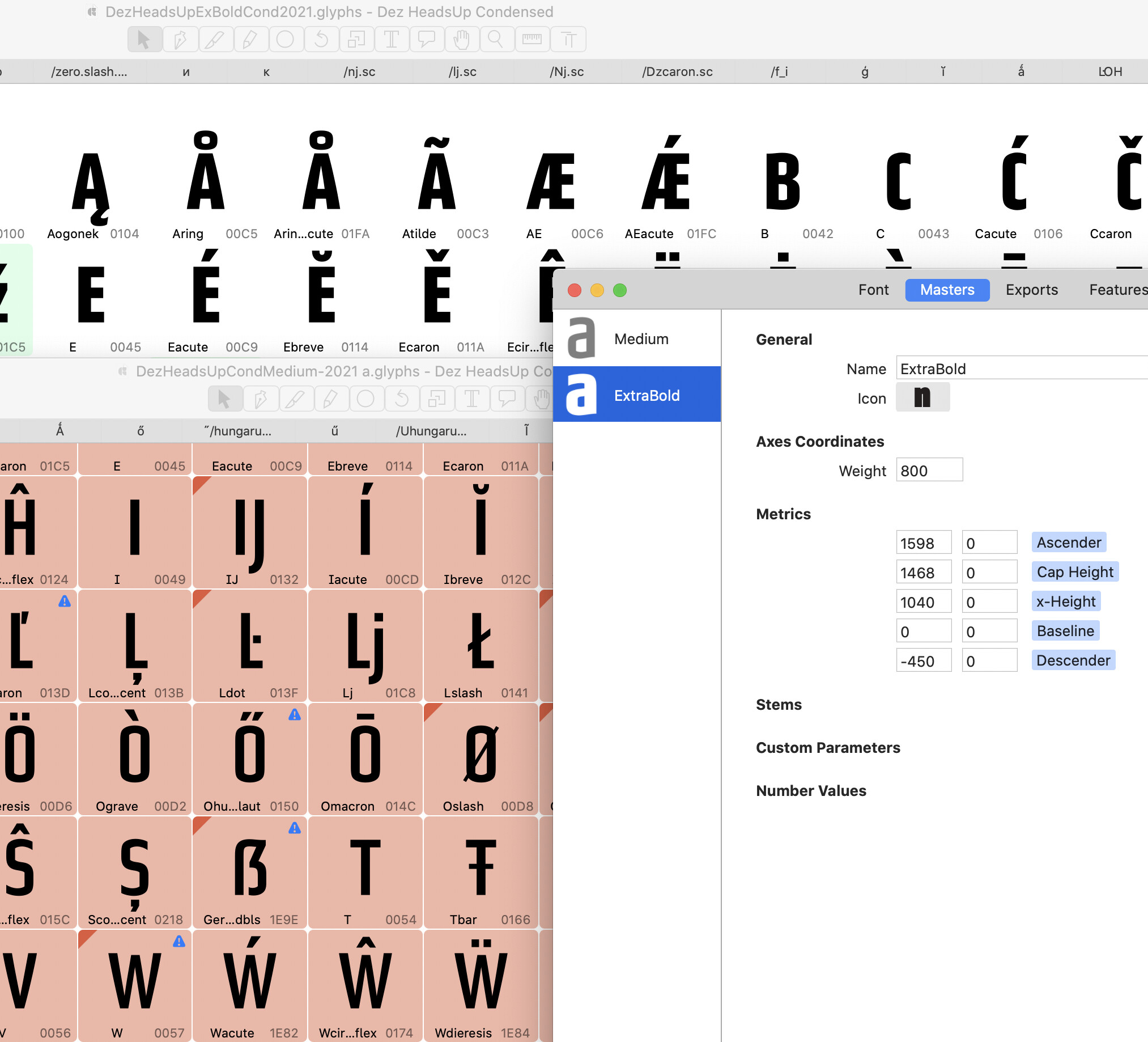
- The list of exports/instances in the Font Info > Exports tab.
- Weight axis setting for each Master should be different.
- Set appropriate axis Weight for each Export/Instance.
In your case, if the Exports tab is empty, I’d probably consider setting up an Instance for each Master with the + icon in the lower left of the Exports tab. And add a Bold instance with a Weight axis coordinate between the Medium and ExtraBold masters’ Weight values.
If that’s all set up, then it may help to be more specific in what’s going wrong or what error messages you might be seeing.
As also mentioned, the glyphs need to be compatible (same number and order of shapes, anchors, etc.). If that’s the issue, there are some tools to help. The tutorials for multiple masters have not yet been updated for Glyphs 3. Fix Compatibility is now Filter > Shape Order. Also, View > Show Master Compatibility can be helpful in tracking down why glyphs might not be compatible.
1 Like
What does the orange bar on the top of affected glyphs mean? I would hope for a descriptive error code or at least find something under help search for “orange bar”?
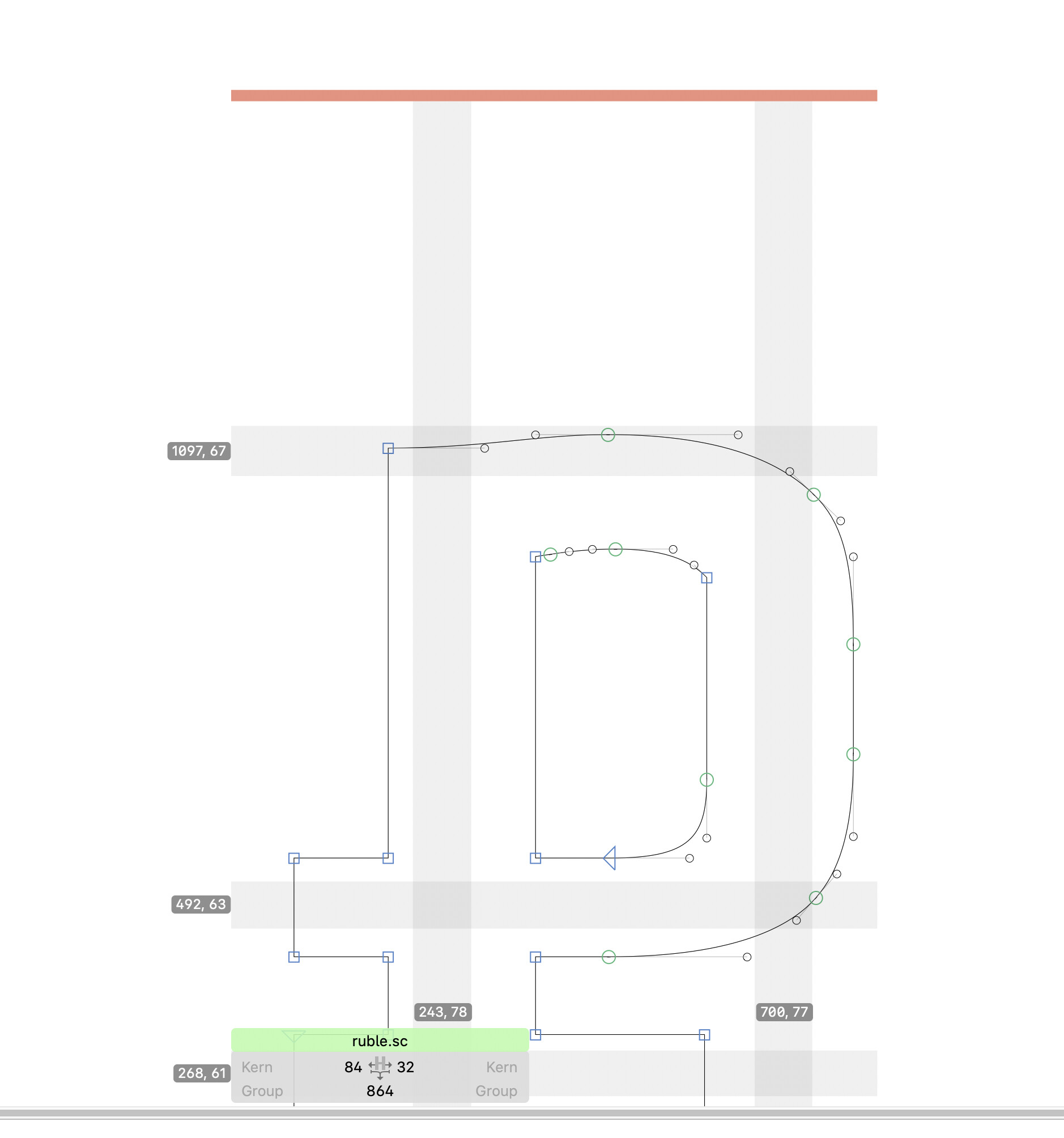
It means they aren’t compatible.
With what and in what way?
With the other ruble.sc glyph(s).
I can’t see the other one so I can’t fix it. I feel that I am missing the “ahah” moment 
If it is anything like mine usually are it is a difference in the node count. BTW, the orange bar is, IIRC, called red in the manual.
Is there a way to see the glyphs superimposed to help trace the error?
Under View, Show Nodes > and make sure the first two items are selected. Then click the eye icon in the right sidebar of the other layer you want to see. The other glyph will be offset so don’t let that throw you off.
I will give that a try, thanks!
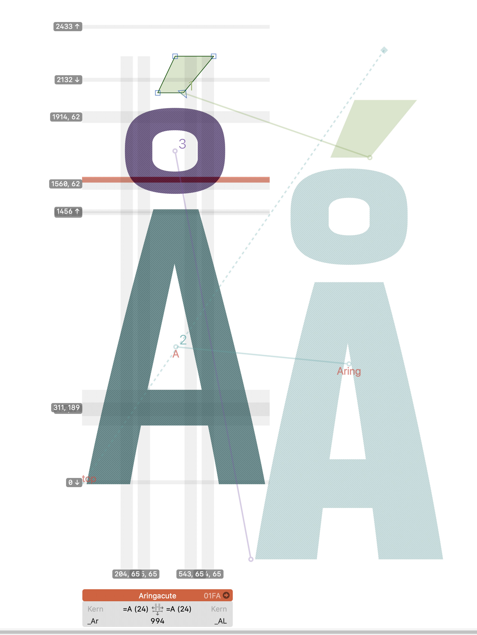
That plus “Show Master Compatibility” showed me this:
Looks like anchor position in one. Does that matter?
The acute on top has a triangle in the lower right corner, what do I do with it?
The position of the anchors should be OK so long as you have an equal number of matching anchors. The little triangle is the start node of that path and shows the direction too.
I think the one on the left has two composites in it. Pretty sure that would trigger incompatibility.
If the connecting lines in the Show Master Compatibility are crossing is usually not a good sign.
There are several problems in the glyph in the screenshot:
- There is a “top” anchor in the other layer, not so in the active. (the blue dotted line going from bottom left to top right).
- It seems that the active layer is made from A+ring+a manually drawn acute. The other master has Aring+manually acute.
Switch between the masters (Cmd+1, 2) and have a look at the red words. They tell you what is in on master and not in the other.
And on top of the incompatibly, there are a hole lot wrong hints. I would remove all of them.
Thanks! I will give that a try!
What an incredible mess I have made.
1 Like
so the AH-HAH! is to select all and “correct Path Direction” on both masters?
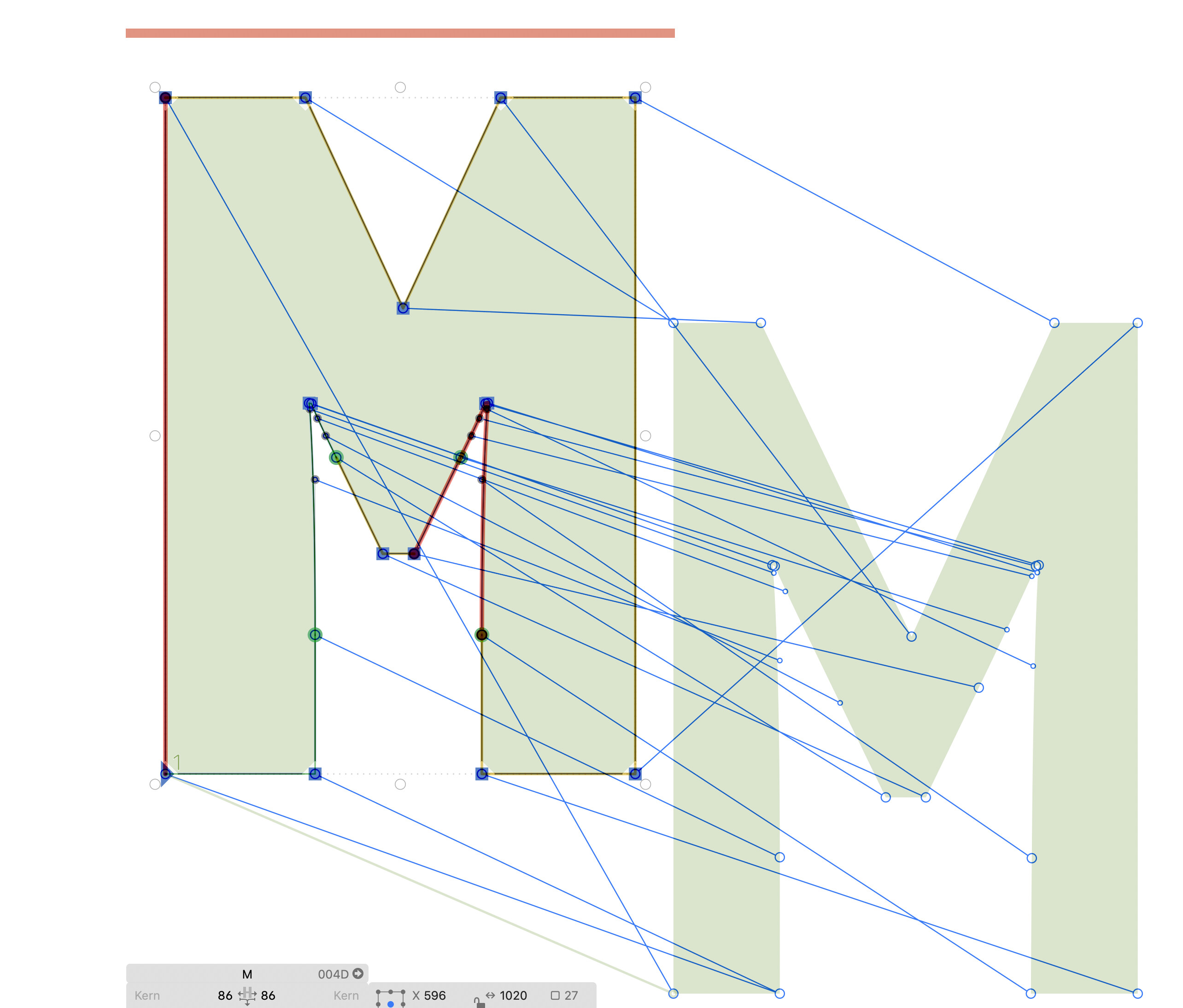
Fix the start point first. You can drag the start point in the other master (the ring in the bottom right).
I assume the two masters do not have the same number of nodes. Hence the red segments.