It would be really usefull to have a way to insert partial masters. The brace trick is good for the cases you show in the tutorial, but if you want to really have control over the regular weight for instance, you really need to have a third master.
I always have a master for the regular weight, but there are a lot of glyphs that could simply interpolated between the two extremes, so always having this full master in the middle is a lot of work. Also this could help in controling the coordinate rounding problems that glyphs has. Each outline seems to have its own register point when interpolating, which makes it really hard to predict the outcome of interpolations.
The idea of a partial master would be perfect, for people that worry about the two stems of an ‘H’ having exactly the same width, for instance. but most importantly for a bunch of glyphs that need to be design specially for the regular weight.
What you describe are inherent problems of coordinate interpolation in outline formats and not specific to Glyphs. Every x coordinate and every y coordinate is interpolated independently. The coordinates know nothing of the stem the designer had in mind, they are just sitting somewhere on an outline. And their interpolated position must be rounded to the grid you specify. You can reduce the potential rounding error with a finer grid.
And how would the proposed solution be any different from brace layers, other than that it offers less flexibility? A brace layer, after all, can be placed anywhere in the design space. A position that makes sense for one glyph, may not necessarily make sense for another.
Or, you can create a full intermediate master and reinterpolate the master layers of the glyphs you want to leave out. You can do that with a simple script.
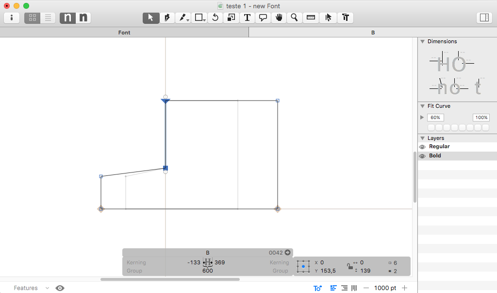
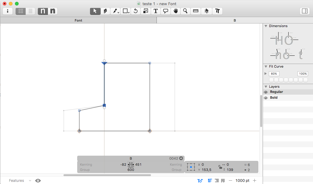
I have been trying to understand the interpolation in glyphs because I see nodes being rounded to apparently unexplainable positions, after all the effort I’ve made in trying to control them. The only conclusion I could arrive at is that each outline is handled with its own reference point. This doesn’t happen for instance in superpolator where the reference point is the same regardless of where the object is in space. please see this example.
These two pictures show two masters. In both Masters, the selected points have a zero X value, as you can see.
This can actually generate lots of inconsistencies, specially if the design is complex or if you use components that have to sit accurately next to each other.
I didn’t know this, I have to read the tutorial with more attention. Thanks.
That sounds great, is there a script like that available?