I am wondering if I got a thinking twister or if GlyphsApp might display quadratic curves with hidden oncurve points?
As far as I thought I understand a quadratic curve can only have one control point and that’s also how CoreGraphics treats them “The element holds a control point and a destination point”. But GlyphsApp presents them with oncurve points and a bunch of apparent offcurves, where the connecting lines tangent the path (and that’s where I’d expect the next oncurve to be actually).
So is that on purpose that you “hide” some oncurves, or am I stupid, as often?
I need to know because we’re trying to debug kinks of a very complex variable font and different analyzing tools happen to render the glyphs differently …
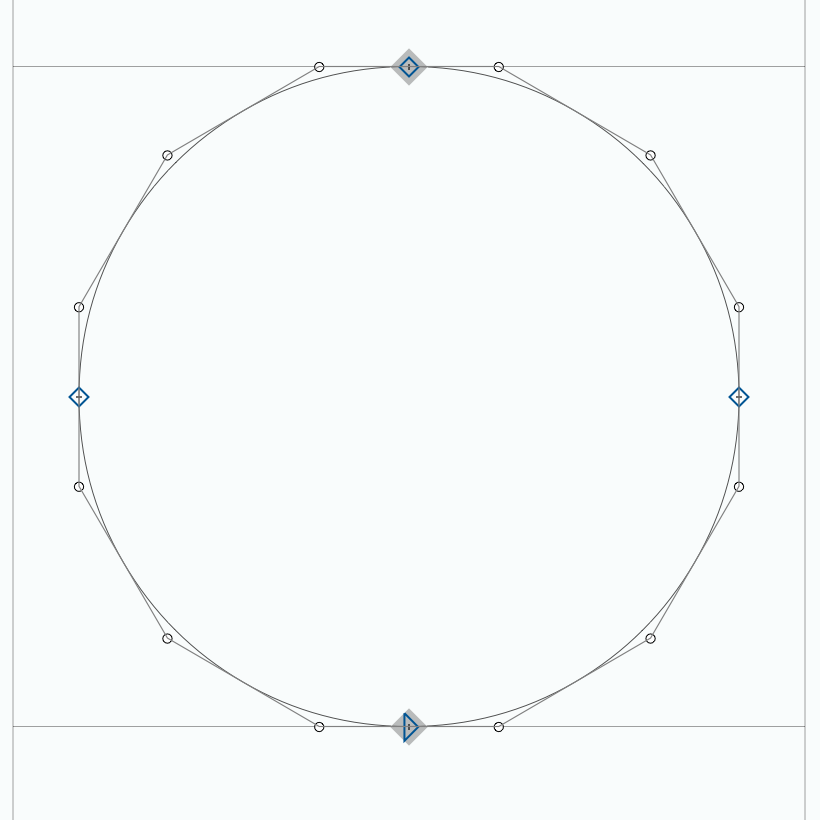
Those points are not hidden. There are no points to hide. To render the segments, points are implied halfway between the offcurve points.
That way you even can have a path without any oncurve points.
To render a quadratic segment, you need oncurve+offcurve+oncurve.
If the curve can handle the ‘missing’ oncurve points (actual points can handle different proportions between two offcurve points) it has several advantages to omit them (smaller file size, avoid kinks and rounding errors).
… which are only 16 points (as in the Glyphs representation), but it shows more points. This is what my CGPath does as well.
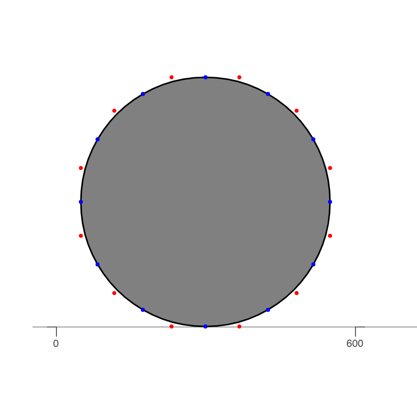
The here astersiked nodes are highlighted there to show that they are oncurve.
The blue nodes seem to be more illustrative but misleading.
If you look at your outlines in OTMaster it displays the implied nodes and even worse if you move any of the points, all the extra nodes are actually added to the data. ;(
It’s baffling, because when parsing the path with CoreGraphics it always returns those “extra” oncurves, as there is no other way in CG quadratic curves than having only one control point. So there must be way to omit those somehow, but I don’t know what’s the method behind them. Apparently CG thinks those points are there. That’s probably why OTMaster shows them as well.
I see that Samsa renders it like GlyphsApp does, and in the source I found this bit, where the comment also says something about “implied” oncurves and 2 consecutive offcurves:
//...
if (pt[2] == 0 && pt_[2] == 0) // if we have 2 consecutive off-curve points...
	contour.push ( [ (pt[0]+pt_[0])/2, (pt[1]+pt_[1])/2, 1 ] ); // ...we insert the implied on-curve point
//...
// - we’ve already fixed things so there are never consecutive off-curve points
//...
if (pt[2] == 0) { // off-curve point (consumes 2 points)
//...
“Now for the trick: if each Pn is an on-curve point, and each Cn is a control point, and P2 lies exactly midway between C1 and C2, P3 lies between C2 and C3, and so on, then this is a compactable curve: if we know C1 and C2, we know P2, so we don’t have to list it explicitly, we can just leave that up to whatever parses the glyph outline.”
This starts to look like the answer I was looking for. I assume GlyphsApp does sth similar here?
I am still nagging because my understanding of Quadratic curves requires only one control point and also as Just points out here: “implied on-curve points are still on-curve points.”
There is a difference what you need to render the curve and what you need to store in the font. Rendering needs one offcurve point between two oncurve. But you don’t need to store them.
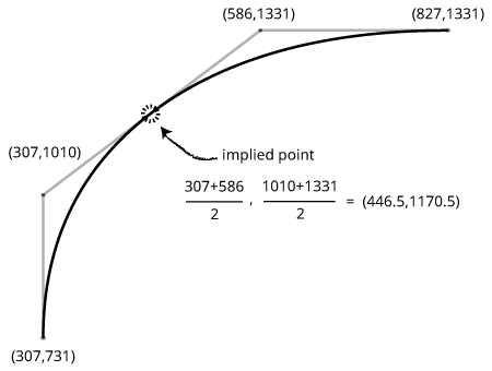
There are two off-curve points between the on-curves! Does this mean that we’re suddenly using cubic Bézier curves in our TrueType outlines? Nope, the font is doing something clever here to save space: there is an “implied” on-curve point located half-way between the off-curves points. Software handling these curves needs to insert the implied on-curve point.
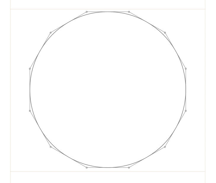
In your example, you could remove all the oncurve points (because all are halfway between offcurve points), and that would still be a valid TrueType curve.
Good explanations here already. You might like to take a look at the SamsaGlyph.svgPath() method. Samsa performs an initial loop through the points, during which it inserts the implied points, then a second loop where it converts to quadratic SVG.
By the way, Samsa preserves FUnit coordinates in its SVG paths — in the font file these are always integers, but the implied points can be on the halves, and you will see those in the SVG.